
ADF Active Filters
ADF Active Filters
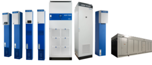
ADF active filters are advanced, computer-controlled current sources enabling generation of electricity of any waveform. The main task of the filters are to compensate for current and voltage distortion in the electrical network generated by non-linear receivers. Thanks to the use of ADF active filters it is possible to obtain a longer service life of devices, reduce electricity consumption and losses resulting from its transmission, increase the efficiency of rotating machines powered from this network, obtain the load balancing effect as well as infinitely passive reactive power compensation. On the website you will find the theory of ADF active filters operation, dates for planned trainings and forms for requesting the measurments and contact.
Electricity Quality Academy
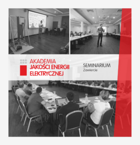
On June 27-28 in Zawiercie the fourth edition of the Electricity Quality Academy took place. During the course, the problems of current and voltage strains occurring in the network as well as their impact on the operation of devices in production plants were discussed.
The Electricity Quality Academy organized by ANIRO enables broadening the knowledge of the people managing the operation of equipment, in relation to technological changes taking place on the market, learning about modern devices for improving electricity parameters, methods of protecting devices operating in the electrical network against negative effects of occurring strains, presenting advanced methods of improving parameters the quality of electricity and increasing the efficiency of equipment.
The course was attended by maintenance engineers, automation engineers and electricians, who during the Academy had the opportunity to present the cases they encountered and exchange experiences related to the location of the sources of distortion and the applied solutions.
The June edition of the Electricity Quality Academy was created in cooperation with the following companies: Lumel, Artech and Inducto. Hence we would like to thank our partners for participation and organization of the meeting.
ACTIVE FILTERS THEORY
In most technical problems related to the generation, transmission and use of electricity, it is assumed that we are dealing with linear electric circuits. Among the energy receivers more and more often we find receivers for the formation of sinusoidal current and voltage waveforms. These are so-called non-linear receivers, to which we can include all receivers that are not purely resistive. Non-linear receivers lead to harmonic currents and voltages. Harmonics are one of the oldest disturbances of power electronic systems. The problem of higher harmonics is constantly growing and the risks associated with it should be taken seriously.
The concept of harmonics comes from acoustics, where they are referred to the vibrations of the string. In the case of power electronics or electrotechnics, the harmonic is defined as the component of the waveform with the frequency of the fundamental component.
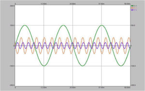
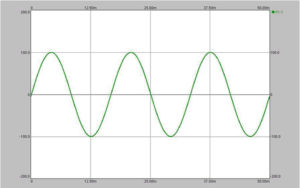
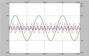
The 50 Hz basic component and the fifth and seventh harmonics of the signal 250 Hz and 350 Hz.
The non-linear receiver generates distorted harmonic current. This current causes a voltage drop on the transformer and thus induces a deformable voltage that powers all the receivers in the system. Purely resistive receivers in the circuit will also be exposed to harmonic currents, despite the fact that it is a purely linear receiver.
The amount determining the distortion of voltage or current through the presence of higher harmonics is the so-called THD (from Total Harmonic Distortion). The THD factor can be referred to the current (THDI) as well as the voltage in the tested circuit (THDU):

THD as a quotient of the effective value of higher harmonics to the value of the effective fundamental component of the voltage and current.
The upper limit of the summation is usually n = 50 (fiftieth harmonic). Harmonics, due to the direction of rotation of vectors with respect to the basic component, are divided into:
+ compatible: 3K + 1 – harmonics on the order of 1,4,7,10 … ..
+ opposite 3K + 2 – harmonious order of 2,5,8,11 … ..
+ zero 3K + 3 – harmonics of the order of 3,6,9,12 …. (generated mainly by non-linear 1-phase receivers, which add up in the neutral conductor).
In the circuits under consideration, so-called interharmonics that are not integral multiples of sub-components and subharmonics that have components less than the fundamental frequency.
The commonly occurring non-linear load is the 6-pulse rectifier, typically found in inverters. The n pulse rectifiers generate harmonics of the order k (n +/- 1). For a 6-pulse rectifier, these will be 5, 7.11 and 13 harmonics of the current. For a 12 pulse rectifier, they will be harmonics of the order of 11.13,23,25. Consider the current consumption by a frequency converter that is rated 70.7A from the 50Hz network.
In practice, the inverter is equipped with a 6-pulse rectifier, which mainly generates harmonics of 5 and 7 order:
The result is that the receiver can see the sum of these processes.
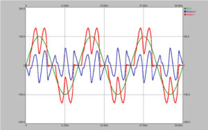
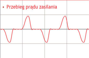
Finally, we get a distorted sinusoidal waveform which amplitude can be several dozen percent larger than the basic one. The basic component was 70.7A. The sum of harmonic currents is: 30.8A. As a result, the drive draws a current of 77, 14A, not 70, 7A.
Harmonic currents force the receivers to flow more electricity. This leads to excessive heating of the installation. Power cables and protections should be oversized, rated for continuous current with regard to current harmonics.
List of typical receivers that cause current and voltage distortion:
Destructive influence of deformed current and voltage:
Impact on engines and generators:
What are the ways to deal with higher current harmonics?
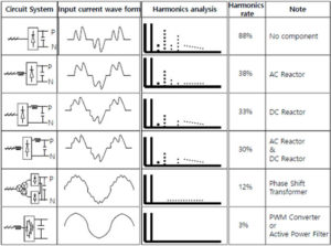
The simplest and cheapest method is to use a reactor which changes the impedance of the network to a certain extent. In the case of the inverter’s drive system, the input choke or built-in DC circuit limit the current harmonics to around 30-40% depending on the load size. The use of a 12 pulse rectifier is possible when connecting the system to two transformers (one connected in a Y, the other in a delta). Harmonic limitation up to 12%. Passive filtration solutions are also available on the market. These are typical LCL filters, whose electrical parameters have been selected for the appropriate operating point of the drive (filtration <8% assuming that the load is greater than 80%). However, this is an uncertain solution introducing additional oscillations into the system. LCL filters are usually very large and expensive. This kind of solutions is slowly stepping down. The best and most reliable solution is to use an active filter that can dynamically respond to demand and quickly compensate for current and voltage harmonics. The offered filters of the ADF series can additionally compensate for reactive power (both capacitive and inductive), load symmetrization and eliminate the phenomenon of flickering.
Use
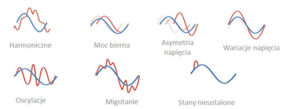
ADF Digital Filters Available for all installations, facilities, and power quality in general. When we talk about energy quality, we mean:
If we lived in a perfect world, most of us would expect our equipment to work as advertised, efficiently and without problems, and present itself nicely. It is also easy to imagine the voltage and current – we see it as the perfect sinusoidal waveforms drawn on a piece of paper or on the monitor screen. However, in reality our expectations turn out to be a simple fantasy, and if we looked into our electrical sockets, it would turn out that the electricity does not look as expected and significantly deviates from the waveforms from the monitor screen.
The truth, however, is that energy in any network is usually imperfect, defective, burdened with errors in accordance with natural laws of electricity, but also due to the impact of equipment that is part of the system. Effect? Deterioration of equipment operation parameters, defects, energy losses, strange events seemingly unrelated to the equipment … all of which require downtime to assess their condition and make possible repairs.
Most of you have experienced unexpected, unnatural equipment failures, for example light bulbs. Most probably also experienced abstractly high electricity bills. These are just some of the symptoms that may be a consequence of poor power quality.
The perfect solution that is able to comprehensively take care of the electricity quality are ADF Aniro active filters. With only one device, it is possible to compensate for passive power, harmonics, elimination of flickering, load balancing.
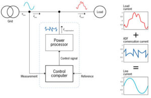
The active filter works on the principle of active headphones. The headphones have a built-in microphone that collects background noise. Next, the headphones generate a course in opposite phase, which after adding up with the measured signal – in the result we obtain silence:
The image below illustrates the principle of how the filter works: